PCB stackup, signal integrity and controlled impedance Software and test systems for PCB assembly and repair
CITS 880s
Test system for impedance-controlled PCBs
- now with launch point extrapolation (LPE)
Finer geometries and thinner copper can present a challenge for fabricators measuring impedance on leading edge PCBs. The CITS880s answers that challenge with the introduction of Launch Point Extrapolation (LPE). LPE extrapolates the TDR response back to a point close to the start of the transmission line effectively allowing to users more accurately to measure the instantaneous or incident impedance of the line.

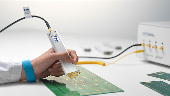
IPDS-100 groundless differential probe
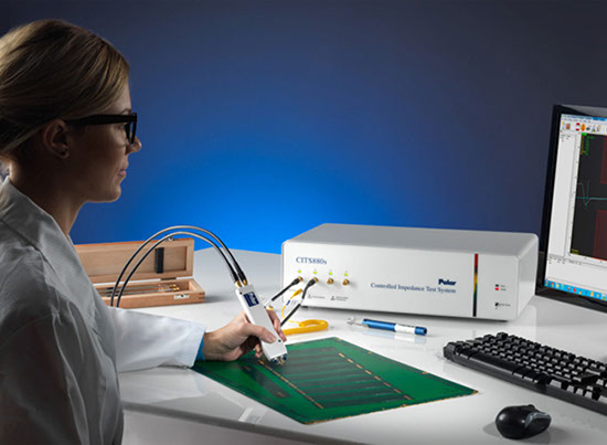
CITS880s Controlled Impedance Test System
<
>
CITS880s –
impedance measurement made easy
- Designed for PCB production environments
- Ideal for CEM inwards inspection
- Measures PCBs and test coupons
- Groundless differential test
- Customer conformance reports
- Automatic data logging
- Enhanced accuracy for close coupled traces
- Multi point traceable calibration
- Optional crosstalk test facility
- Generate CITS test programs with Speedstack
- PolarCare maintenance and support
Polar IP impedance test probe footprints – for CITS880s and legacy CITS
Controlled impedance PCBs are used across a broad range of applications to help ensure high frequency signal integrity. Designers invariably specify these types of PCBs whenever the edge speeds of digital signals are faster than 1ns or analog signals climb above 300MHz.
The characteristic impedance of a PCB trace is determined by the dimensions of the trace and the properties of the PCB material which can vary from batch to batch. To control trace impedance PCB manufacturers usually vary trace width to compensate for different batches of PCB material. Historically, they were then forced to use specialist laboratory equipment such as a time domain reflectometer (TDR) to measure the characteristics of a representative trace etched on the board or a test coupon. This approach was complex, expensive and far from ideal in a production environment.
Many electronics designers – especially those pushing performance boundaries in the defense/aerospace, communications and IT industries – are now taking controlled impedance PCBs a stage further by using differential signals and balanced traces to improve noise immunity and reduce timing errors on very high speed interconnects. For PCB manufacturers serving these rapidly-growing electronics sectors, verifying the differential impedance of these balanced traces is now a simple task.
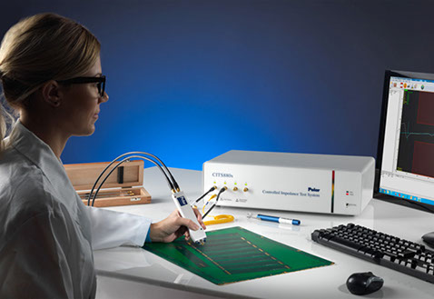
Easy to use
CITS impedance test systems are exceptionally easy to use. Powerful Windows-based software automates every aspect of testing, enabling the entire process to be controlled by a single click of a mouse or footswitch. You simply position the IPS probes, select a test file containing the normal PCB test impedance and tolerance, and press the footswitch. There is no requirement to perform any of the adjustments that are conventionally associated with complex TDR measurements such as setting-up vertical gains, pulse time delays and timebase values. For maximum throughput, the CITS can execute a series of impedance tests automatically, prompting you to reposition the probes as appropriate.
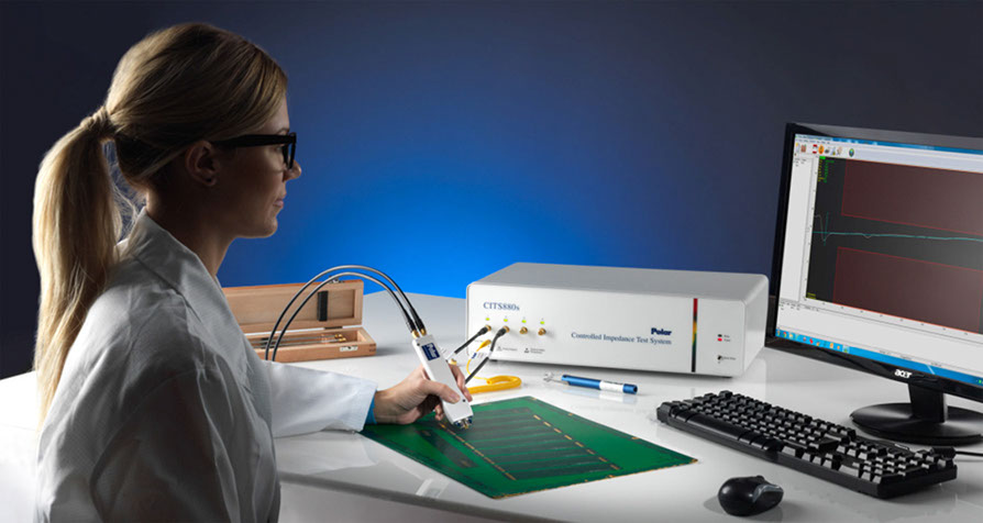
Test results are simple to understand – the CITS automatically processes the data to produce an unambiguous display of characteristic impedance vs distance, and provides clear visual indication of pass/fail status. On fine geometry boards which sometimes exhibit an upward sloping trace, the use of Launch Point Extrapolation (with the approval of the board design authority) will allow you to better correlate the impedance test resutls with 2d field solver (such as the Si8000m) predictions. Use of LPE also makes the measurement far less subjective to the positioning of the test limits.
Automatic datalogging enables test results – together with system set-up data and measurement criteria – to be easily exported to a wide variety of third-party database or spreadsheet packages for real-time statistical process control. The pass/fail status of each test is also made available via opto-isolated signals on the instrument's rear panel, facilitating integration with other factory automation equipment.
All CITS880s now also offer direct export of test results in Excel compatible format.
Traceable measurement activity
Traceable measurement accuracy complements the CITS simplicity of operation. Furthermore, QA specialists still have the freedom to specify complex measurement parameters as well as standard test functions like pass/fail limits, result handling and data logging.
Multi point calibration with reference air lines ensures traceable impedance measurements from under 28 Ohms single ended to over 150 Ohms differential.
You can print test results to provide conformance reports for your customers, store the data on disk for archive purposes or future analysis or export it for real-time SPC purposes. An optional datalog report generator (DRG) accommodates a wide variety of standard forms, for simplicity of reporting. A barcode reader is also available as an option, which enables PCB identification labels to be scanned-in during the test process, reducing handling time and eliminating error.
Design and process control
When considering starting impedance controlled production you will also find the Polar Si8000m controlled impedance design system helps you tailor your customers designs to your production process. It is also ideal in helping your front end team to optimise the incoming data for maximum controlled impedance yield. Working with both CITS and Si8000m will give you a complete solution for impedance test and process control.
For more information on the CITS880s impedance meter or the Si8000m design software, please contact us at germany@polarinstruments.eu
Polar instruments GmbH
Aichereben 16
4865 Nussdorf am Attersee
Austria
+43 7666 20041-0
Fax +43 7666 20041-20
Polar Instruments (Asia Pacific) Pte Ltd
Interlocal Centre, #07-23
100G, Pasir Panjang Road,
Singapore 118523
+65 6873 7470 / +65 6873 7470
Fax +65 6872 7471
mail@polarinstruments.asia
www.polarinstruments.asia
© 2024 Polar Instruments GmbH
|
Distributors:
Fachverband für Design,
Leiterplatten- & Elektronikfertigung