PCB stackup, signal integrity and controlled impedance Software and test systems for PCB assembly and repair
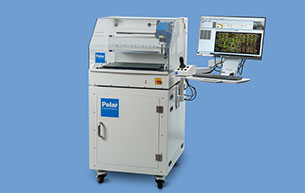
GRS 550
Automated Fault Location on complex PCB´s


Stepper motor control with monitoring of all axes with encoder
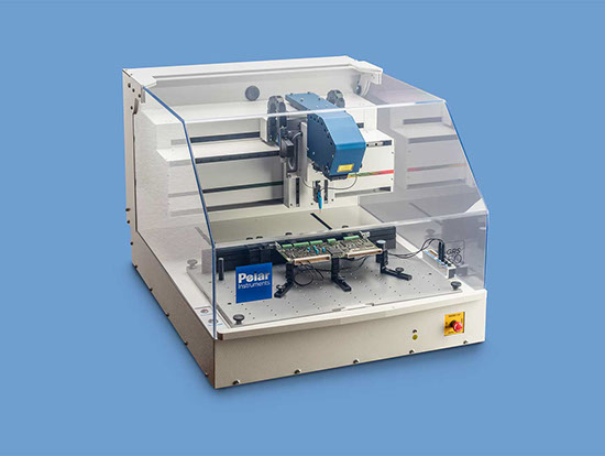
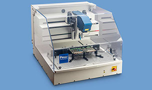
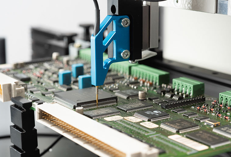
PCB repair system GRS 550
High positioning accuracy enables the contacting of the smallest IC grid dimensions
System with optional base cabinet
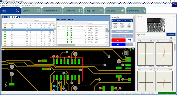
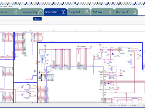
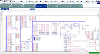
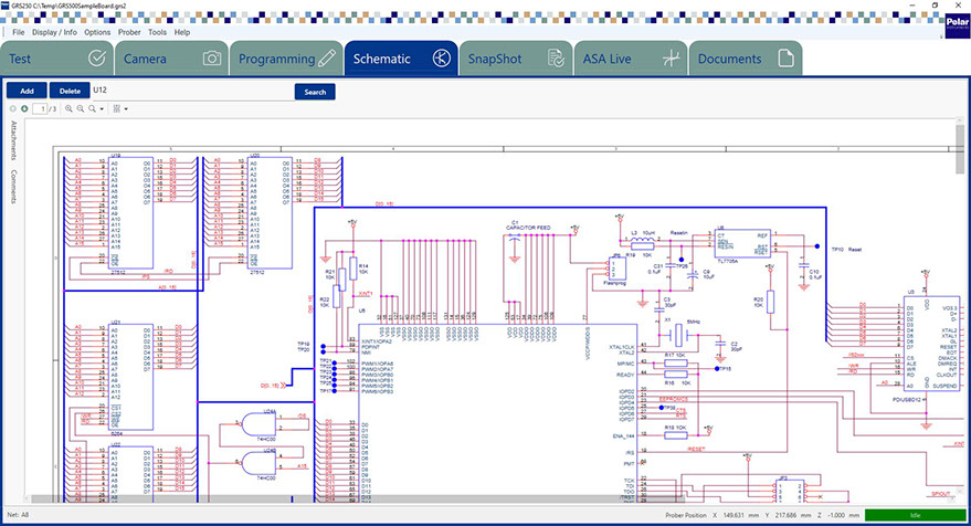
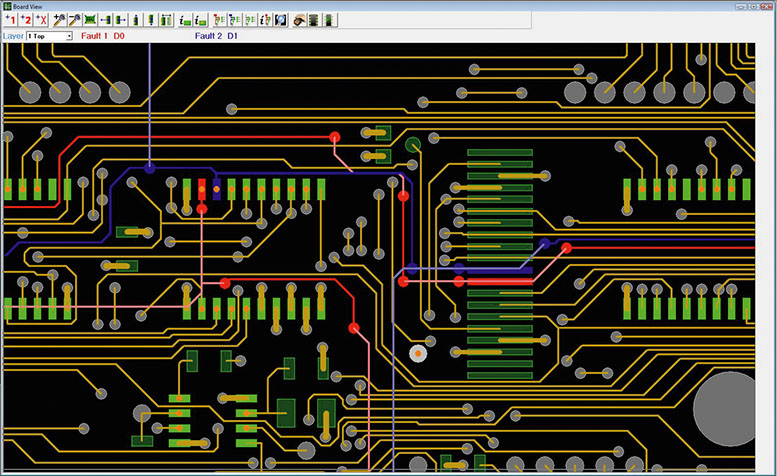
GRS shows the CAD networks on the screen
<
>
Brochure download
Prototypes, short production runs, repair applications
GRS550 helps deliver your new product to market on time and on budget.
Prototypes, short production runs, new product launches all present a challenge in the manufacturing environment. In short series production and prototype build situations, traditional test solutions are often not economic to implement. This leaves your technical team facing the prospect of performing manual troubleshooting. It goes without saying this is labour intensive and not an easy task on densely populated high technology PCBs. GRS is designed as a repair test system, helping you repair and reclaim expensive boards with hard to find faults which otherwise would only be scrapped, saving a costly and wasteful exercise. Designed especially to operate in the following situations – prototyping, with newly launched products, and with production runs that are too small to justify traditional ATE –although you can also use the GRS 550 as an excellent complement to traditional fixture based ATE. If you specialise in prototype or short series production, the GRS is just what you need to keep yields at a maximum. Make best use of your technical staff. You know that troubleshooting complex PCBs is a skilled task and that skilled technicians who can rapidly diagnose PCB faults are a scarce resource. The GRS is designed to help your technical staff put their skills to best use, by helping them rapidly target PCB problem areas and giving them the tools to track down faults in the minimum possible time. Prototypes, short production runs, new product launches, GRS 550 helps deliver your new product to market on time and on budget. The GRS is efficiently programmed from CAD data, troubleshooting programs can be developed in a fraction of the time and cost of a fixture based solution. Over 20 popular CAD formats are supported by GRS.
Contrasting traditional fixture based ATE and the GRS. The strength of a traditional test solution using fixtures is in a high and medium volume environment, but as board complexity increases, the fixture cost associated also ramps up, and the number of boards you need to build to justify a fixture will also increase. Also, it may not be physically possible to access the whole board with a fixture, leaving some areas untested. GRS is a flying probe based system and by using CAD data the GRS ensures you can probe a high percentage of the board. You may ask, „Is fault coverage as high as on a fixture based system?“ This is an area where you need to decide what is best for your application. A fixture based system will typically (though not always) tend to have a higher fault coverage than a flying probe based system. Your benefit from using a flying probe based GRS is that your technical staff can have programs up and running from day one of production, and when engineering changes are made you do not have to write off costly fixtures - sometimes worth upwards of 20 000 Dollars.
The proven Polar GRS550 Flying Probe Test System – now even more powerful with our all new user interface:
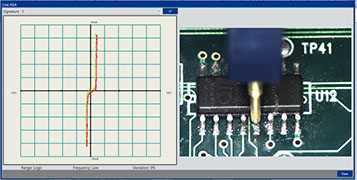
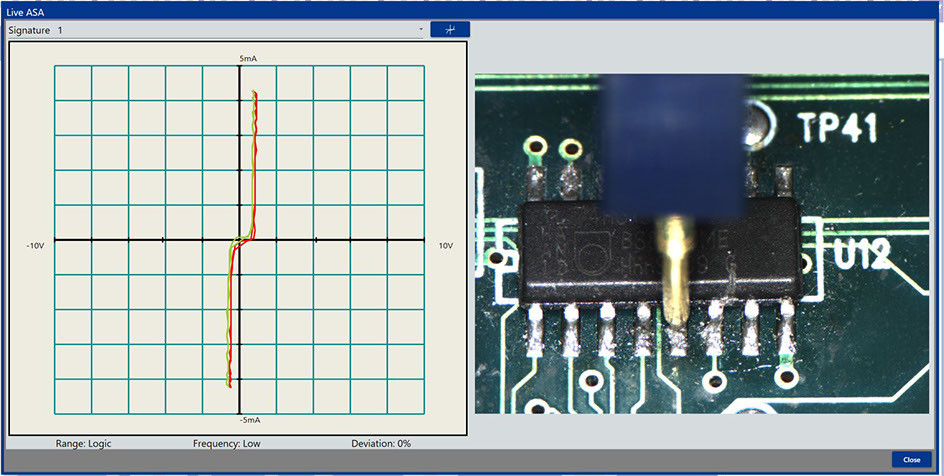
- excellent test coverage using passive nodal analysis
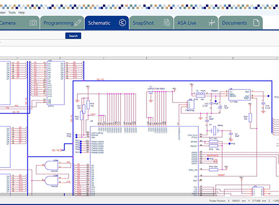
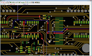
- CAD data visualization für programming and fault location
- Circuit diagram display / paperless repair function
- Manual programming without circuit documentation
- Barcode / QR code reader integration
- Automatic fiducial alignment
- Comprehensive documentation of repair job
- Future proof multithreading software architecture
- Test files compatible with manual GRS200 fault locator
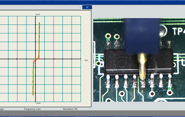
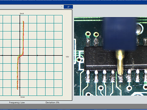
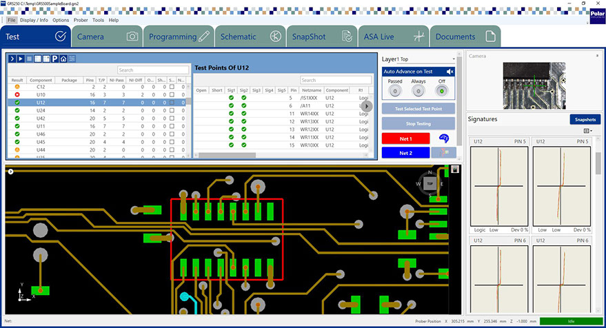
The Test Principle
The GRS 550 relies on the principle of nodal impedance analysis, also known as VI-trace. The board under test ist unpowered, while the test probe applies a current limited AC voltage on all circuit nodes. The specific nodal impedance of each net is displayed and compared with a previously stored reference.
Increase Fault Coverage by adding ActiveTest, ActiveVision, Boundary Scan.
By adding optional modules, the fault coverage of the GRS 550 can be further increased. ActiveTest tests a PCB assembly in powered mode and acquires voltages and signal waveforms on specific nodes. At the same time, the device under test may be controlled using a variety of interfaces.
ActiveVision enables automatic image comparison using the built-in camera system. Use ActiveVision to check displays, switch settings, missing components. Circuit Boards designed for Boundary Scan Test may be analyzed using the Boundary Scan Option.
Designed from the outset for long life, flexibility and low cost of ownership, the GRS 550 will help reduce your costs for many years and is suitable for use on a wide variety of PCBs. You stand to benefit most if you can answer yes to more than 2 of the following criteria:
• Make high value added boards
• Often introduce new products
• Specialise in short series production
• Utilise Functional test or ATE
• Use Boundary Scan
• Need to debug prototypes
Graphical Repair GRS displays the CAD nets on screen and saves your technicians the time consuming process of wading through pages and pages of paper documentation. Built into the GRS design are features designed to speed the troubleshooting process (features Polar has developed using our 35 years of fault finding experience). New in the GRS is a Virtual Xray which allows your technicians to „see“ traces as they run inside the board.
Versatile technology Designed to faultfind on all technologies, the GRS is flexible enough to work on a variety of technologies including surface mount, through hole, right through to BGA and mixed technology boards. And in the event that CAD data is not available, the GRS includes a simple to learn manual programming interface.
Application in service and repair centers, GRS550 is also an invaluable tool in service or repair departments, now faced with more complex and hard to probe technologies. Though designed for use with CAD data, in the event that this is not available for your board, the manual programming interface allows you to „Pick and Place“ components onto a test program. As your knowledge of the board under test grows, you can add known nets to the test program, and start to approach the level of coverage that is obtainable with CAD Data.
The GRS550 supports the following CAD formats:
Bartels Autoengineer
Boardmaker
Cadstar
Eagle
Fabmaster
GenCAD
Gerber
Hyperlynx
Kades-G
IPC-D-356
Lavenir
Mentor Boardstation
Mentor Integra
OrCAD
PADS Power PCB
PCAD
PCAD 2002
Prisma
Protel
Theda
Seetrax Ranger
SuperMax ECAD
TARGET 3001!
Theda
Toshiba
Veribest
Visula
Vutrax
Polar instruments GmbH
Aichereben 16
4865 Nussdorf am Attersee
Austria
+43 7666 20041-0
Fax +43 7666 20041-20
Polar Instruments (Asia Pacific) Pte Ltd
Interlocal Centre, #07-23
100G, Pasir Panjang Road,
Singapore 118523
+65 6873 7470 / +65 6873 7470
Fax +65 6872 7471
mail@polarinstruments.asia
www.polarinstruments.asia
© 2024 Polar Instruments GmbH
|
Distributors:
Fachverband für Design,
Leiterplatten- & Elektronikfertigung