PCB stackup, signal integrity and controlled impedance Software and test systems for PCB assembly and repair
Si9000e PCB Field Solver
Si9000e fast accurate PCB transmission line modeling.
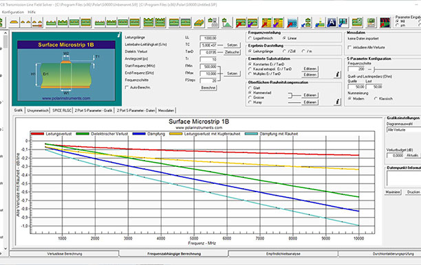
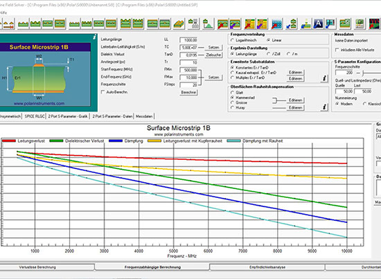
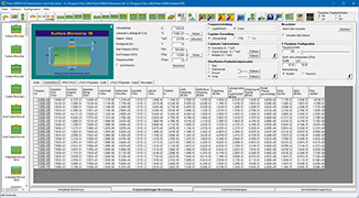
With its fast, accurate, frequency-dependent transmission line modeling, the Si9000e is designed to model transmission line loss, impedance at given frequencies and extract full transmission line parameters over a wide range of popular PCB transmission lines (over 100 structures). Employing boundary element method field solving, the Si9000e extracts RLGC matrices and rapidly plots a range of transmission line information for the structure you are designing. Loss is graphed three ways with clear indication of dielectric, copper and total loss and from 2017 includes Hammerstad, Groisse and Huray methods for roughness modeling:
Links with Speedstack as Speedstack Si
- Si Crosstalk option – Multi line and differential pair (lossless) crosstalk – models coupling between traces
- Si Projects option with Speedstack saves structure groups
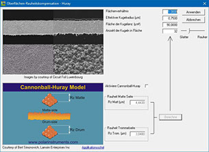
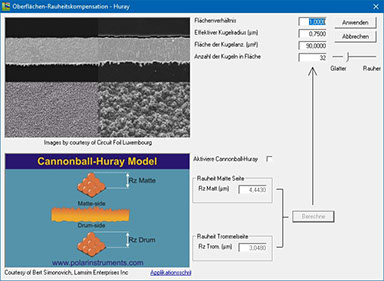
- Roughness modeling – Smooth / Hammerstad / Groisse / Cannonball-Huray
- Inbuilt impedance graphing
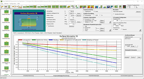
- Graphs conductor, dielectric and insertion loss
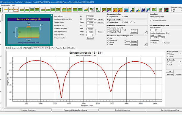
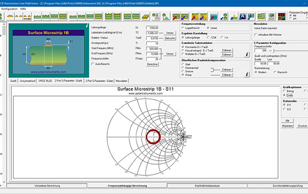
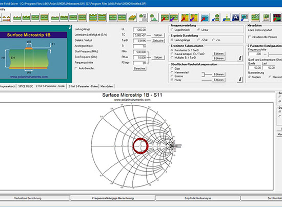
- At-a-glance comprehensive S-parameter charting – magnitude, phase and Smith charts
- Single-ended and Mixed-mode S-parameters charting and data tables
- User defined S-parameter source and termination impedance
- Frequency dependent modeling down to 1KHz
- Go / no go via stub check
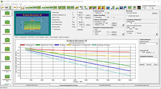
Si9000e graphs all losses – conductor, dielectric and insertion loss. The Si9000e caters for both single and multiple dielectric builds, and comes with the ability to take into account solder mask performance. Mask coverage can be set adjacent, between and above traces. Many Polar customers request frequency-dependent impedance modelling, with particular reference to transmission line losses – the result is the Si9000e. The Si9000e is built on the same proven boundary element field solving platform as the PCB fabrication industry standard Si8000m. Increasing numbers of engineers are using the Si8000m as a rapid and accurate design tool for transmission line impedance – the Si9000e extends the output to extract full transmission line parameters.
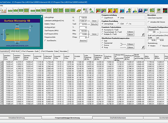
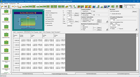
Si9000e PCB field solver extracts insertion loss, RLGC and s-parameters


<
>
Consideration of the copper roughness
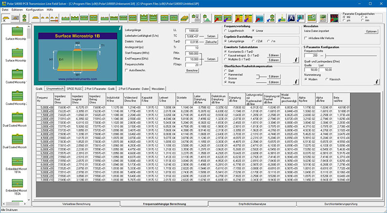
Attenuation calculation
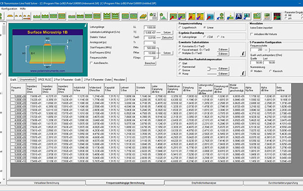
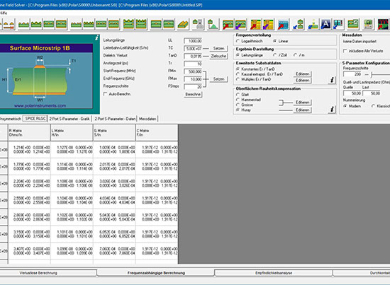
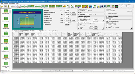
Extraction of the complete line parameters
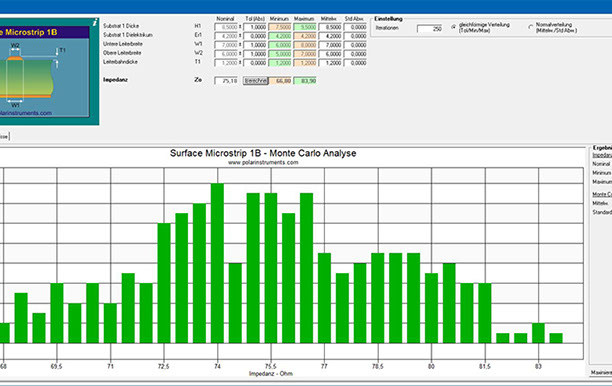
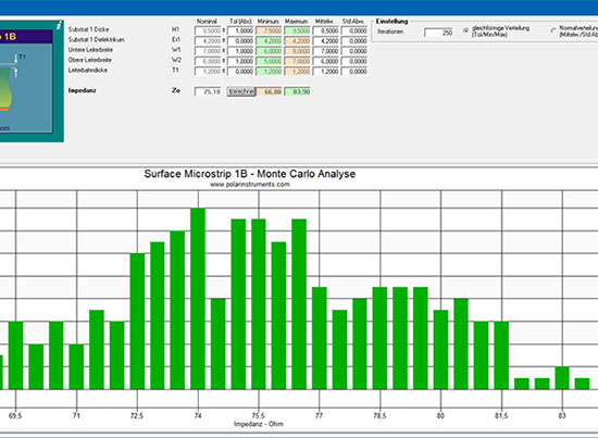
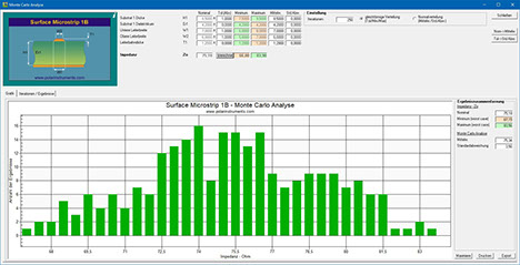
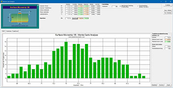
Monte Carlo Analyse
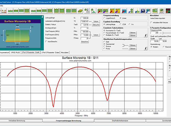
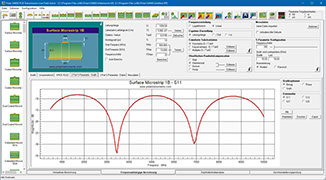
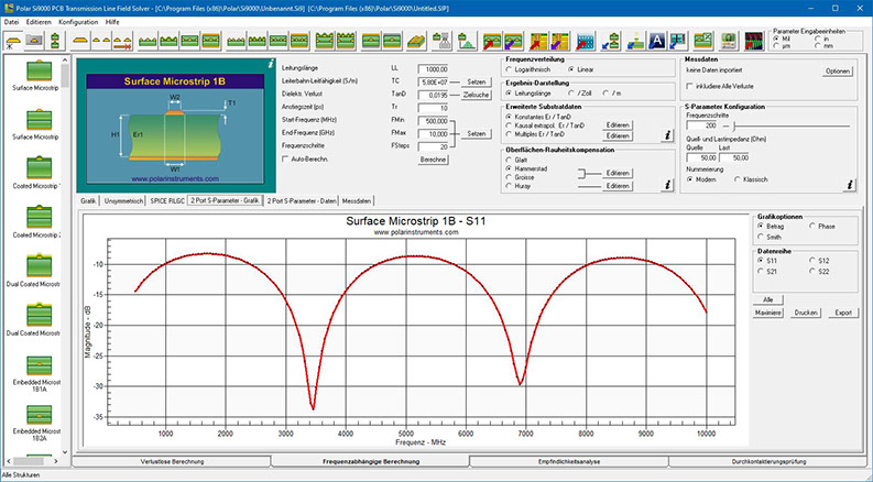
S-Parameter
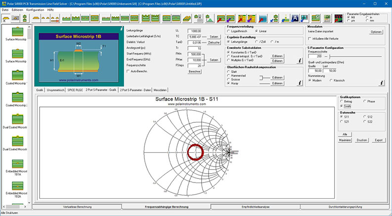
Smith-Diagramm
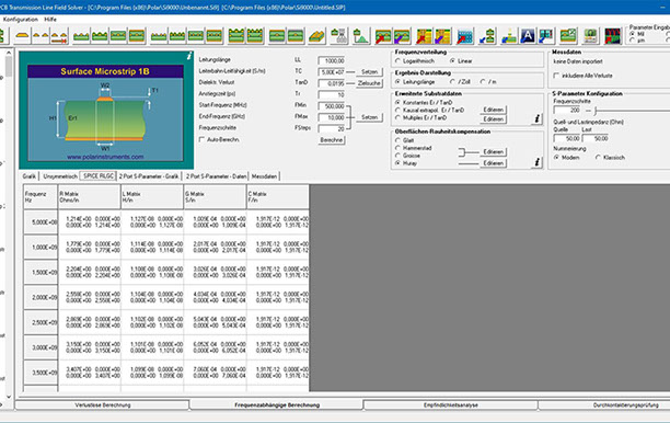
SPICE RLGC Daten
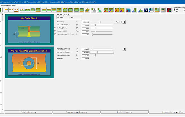
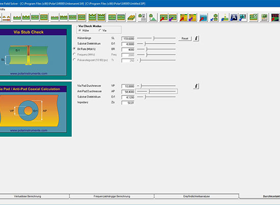
Via-Check
Si9000e fast accurate PCB transmission line modeling.
With its fast, accurate, frequency-dependent transmission line modeling, the Si9000e is designed to model transmission line loss, impedance at given frequencies and extract full transmission line parameters over a wide range of popular PCB transmission lines (over 100 structures). Employing boundary element method field solving, the Si9000e extracts RLGC matrices and rapidly plots a range of transmission line information for the structure you are designing. Loss is graphed three ways with clear indication of dielectric, copper and total loss and from 2017 includes Hammerstad, Groisse and Huray methods for roughness modeling:
• Links with Speedstack as Speedstack Si
• Si Crosstalk option – Multi line and
differential pair (lossless) crosstalk – models coupling between traces
• Si Projects option with Speedstack saves structure groups
• Roughness modeling – Smooth / Hammerstad / Groisse / Cannonball-Huray
• Inbuilt impedance graphing
• Graphs conductor, dielectric and insertion
loss
• At-a-glance comprehensive S-parameter charting – magnitude, phase and Smith charts
• Single-ended and Mixed-mode S-parameters charting and data tables
• User defined S-parameter source and termination impedance
• Frequency dependent modeling down to 1KHz
• Go / no go via stub check
Si9000e graphs all losses – conductor, dielectric and insertion loss. The Si9000e caters for both single and multiple dielectric builds, and comes with the ability to take into account solder mask performance. Mask coverage can be set adjacent, between and above traces. Many Polar customers request frequency-dependent impedance modelling, with particular reference to transmission line losses – the result is the Si9000e. The Si9000e is built on the same proven boundary element field solving platform as the PCB fabrication industry standard Si8000m. Increasing numbers of engineers are using the Si8000m as a rapid and accurate design tool for transmission line impedance – the Si9000e extends the output to extract full transmission line parameters.
Powerful S-parameter graphing
With the Si9000e PCB Insertion Loss Field Solver you can view the full range of 2 and 4-port S-parameters in a single chart window.
Mixed mode
The Si9000e provides a comprehensive range of data presentation in both tabular and chart form with the option of single-ended and mixed-mode S-parameters.
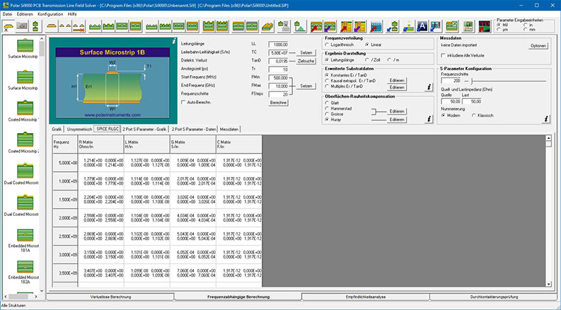
Frequency-dependent calculations
Employing its Boundary Element Method field solving, the Si9000e extracts RLGC matrices and 2-Port (single-ended) or 4-Port (differential) S-Parameters and rapidly plots transmission line information for the structure under design. Graphing against frequency is provided for impedance magnitude, loss (conductor loss, dielectric loss and insertion loss), inductance, capacitance, resistance, conductance and skin depth. The Polar Si9000e runs within the Microsoft Windows environment and provides for simple transfer of table data to external programs such as spreadsheets or databases for subsequent analysis.
Extended substrate tables
The Si9000e frequency-dependent calculations can be refined using extended substrate data. Assign substrate values by frequency band to accommodate material from manufacturers who specify parameters that vary by frequency. Manufacturers may specify, for example, differing values of Er and loss tangent across a range of frequencies.
Frequency dependent calculation range
For frequency dependent calculations the Si9000e calculation engine supports lower frequencies down to 1KHz.
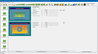
Via stub check
The Si9000 incorporates a Via Stub check that provides a signal distortion of a via stub. The effects of the stub will increase as the stub length and Er increase and the signal rise time reduces. The Si9000e Via Stub Check supports three modes:
• Stub Length, Effective Er and Bit Rate Frequency
• Stub Length, Effective Er and Single Frequency
• Stub Length, Effective Er and Rise Time
•
High layer-count builds
For those working with complex high layer-count builds the Si9000e also links to the Polar Speedstack PCB Stackup Design System and is available in the Speedstack Si package. Using the Speedstack Si allows you to keep all your stack design data in one convenient file – and you can draw library material from your fabricator or from base material suppliers in the Polar Material Partner program.
Designed to save you time compared with traditional methods, the Si9000e lets you choose graphically the structure you need to model and enter the geometric and material data and the range of frequencies under analysis. Select the graphs or table you need and the Si9000e solves for the results. Advanced users may also enter available data for Er and TanD versus frequency – the Si9000e will take these into account.
Single ended:
Impedance magnitude
Skin depth
Insertion loss S21
Conductor loss dB
Dielectric loss in dB
Propagation velocity
Propagation delay
SPICE RLGC
2 Port S-parameters
Differential:
Impedance magnitude
Skin depth
Insertion loss S21
Conductor loss dB
Dielectric loss dB
Differential prop velocity
Differential delay
Odd mode Z magnitude
Even mode Z magnitude
SPICE RLGC
4-Port S-parameters
Si9000e optiones:
XFE option – provides crosshatch return path modelling for flex and flex-rigid PCBs
Si Crosstalk option – Multi line and differential pair (lossless) crosstalk – models coupling between traces
Si Excel Interface option – Microsoft Excel® interface option for lossless calculations in Si8000m/Si9000e
Projects option with Speedstack saves structure groups
Polar instruments GmbH
Aichereben 16
4865 Nussdorf am Attersee
Austria
+43 7666 20041-0
Fax +43 7666 20041-20
Polar Instruments (Asia Pacific) Pte Ltd
Interlocal Centre, #07-23
100G, Pasir Panjang Road,
Singapore 118523
+65 6873 7470 / +65 6873 7470
Fax +65 6872 7471
mail@polarinstruments.asia
www.polarinstruments.asia
© 2024 Polar Instruments GmbH
|
Distributors:
Fachverband für Design,
Leiterplatten- & Elektronikfertigung